|
THE CARTRIDGE COLLECTOR'S EXCHANGE |
|
|
Home of the Old Ammo Guy's Virtual
Cartridge Trading Table
Picture Page April 2017 Please note: Unless otherwise indicated, the pictures on this web site are my property, and should not be used by anyone without crediting the source. PLEASE ALSO NOTE: Beginning May 1st, I will temporarily stop taking orders for items from my web site, but will resume taking orders November 1st. During this break I hope to do a little 'dusting and cleaning' with the anticipated goal of updating my web site a bit. I will still continue with my monthly write-ups, and welcome your emails with questions about cartridges you'd like to identify or are wanting to sell, or to just say hello. Thanks for bearing with me.
Not your ordinary shotgun shell crimper........
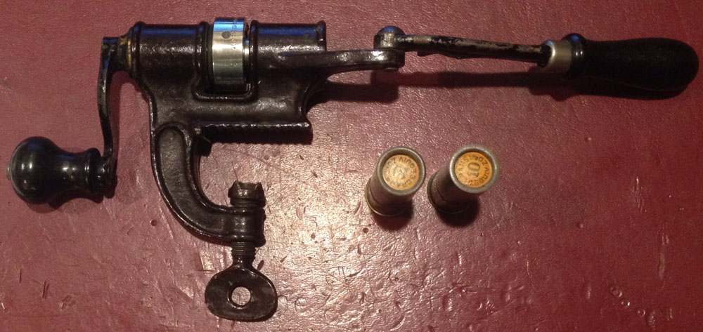
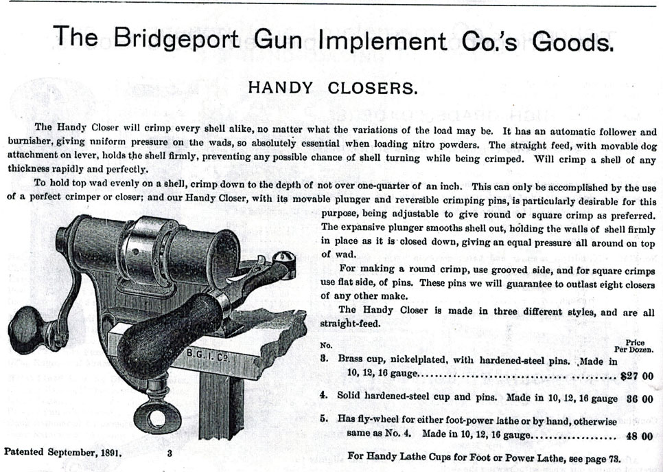
The shotgun shell crimper shown here was made by the Bridgeport Gun Implement Company (BGI) sometime around 1900. It looks and functions similarly to the many other brands of crimpers that were available at the time, and that are still quite commonly found today. Like the others, it is made of japanned steel, has a screw clamp for attaching it securely to the work surface, and two handles, one for pushing the shotgun shell against the crimping head and the other for rotating the crimping head to form the crimp. What differed on this crimper was it's shiny, nickel-plated crimping head which was marked in not-so-subtle, bold lettering 'reversible pins for round or square crimp' with a patent date.
A search for information on the crimper eventually lead to the 1899 Hartley & Graham Arms and Ammunition catalog (available from Cornell Publications-www.cornellpubs.com, along with an impressive 5000+ other catalogs and gun manuals). The catalog states that Hartley and Graham were the agents for The Union Metallic Cartridge Company, The Remington Arms Company, and The Bridgeport Gun & Implement Company; in actuality, they owned all three companies. This crimper was listed in the catalog as the #3 Handy Closer, which sold for $27 per dozen, ($2.25 each). Unfortunately, the description provided little in the way of directions for using it, but did state that the crimper's 'reversible pins' were 'adjustable to give round or square crimp(s) as preferred'.
. . . . Which brings me
back to the first clue I had that this was not your
run-of-the-mill crimper, this being the
markings on the crimping head. These are in two lines that go around the
outside of the head, .
.
With the patent
drawings and specifications, or perhaps in spite of them, I eventually
figured out how the crimping head was removed. As lawyers are involved in
the patent process seemingly for the sole purpose of making
Having removed the
head from the crank handle shaft (upper left
. . . .
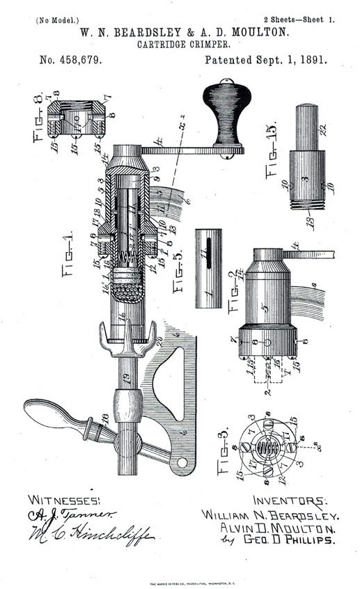
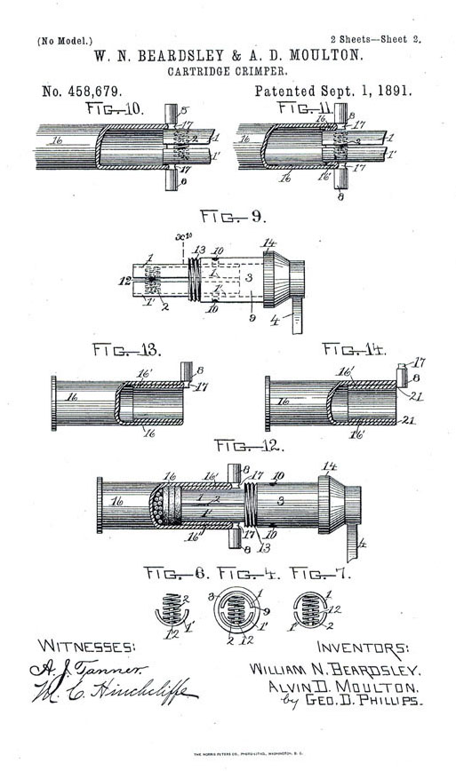
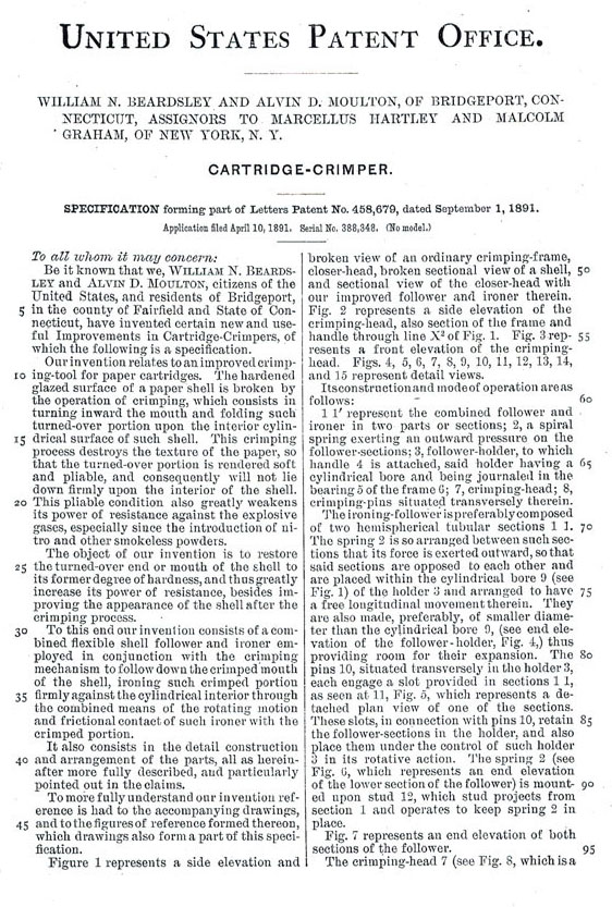
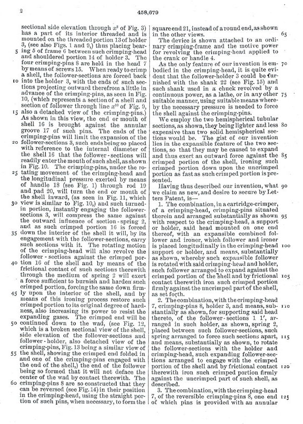
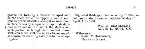
. . . Following are the patent drawings and specifications pages: .
. . . . .
. . . . .
. . . . .
. . . . .
. . . . . . . . .
|
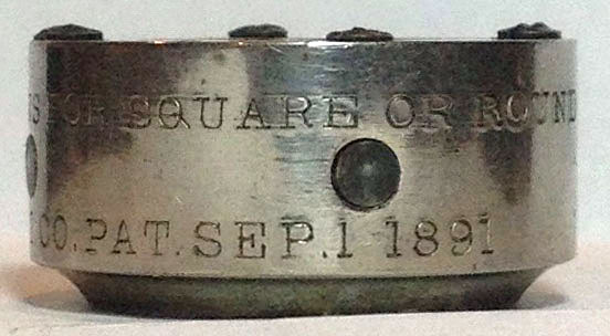
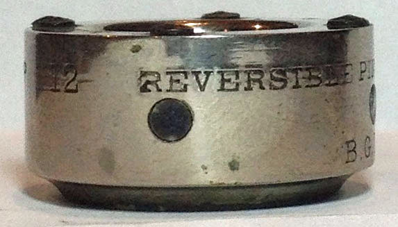 as can be seen in the set of four photos here.
The top line reads 12 (gauge) REVERSIBLE PINS FOR SQUARE OR ROUND CRIMP.
The second
as can be seen in the set of four photos here.
The top line reads 12 (gauge) REVERSIBLE PINS FOR SQUARE OR ROUND CRIMP.
The second
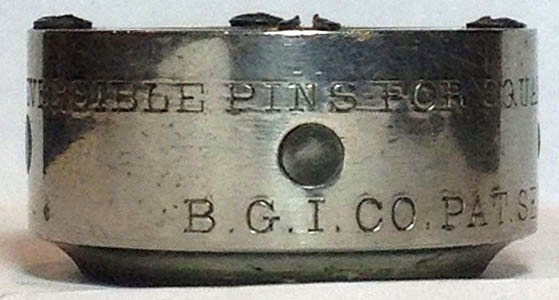 line
reads
PAT. SEP.1 1891. Searching on this patent issue date, I was able to locate the patent on the US
Patent and Trademark Office web site (www.USPTO.gov). I have included copies
of the patent drawings and specifications at the bottom of this page. The
patent was issued to W. D. Beardsley and A. D.
Moulton, who assigned it to BGI. I have no idea what
difference the
line
reads
PAT. SEP.1 1891. Searching on this patent issue date, I was able to locate the patent on the US
Patent and Trademark Office web site (www.USPTO.gov). I have included copies
of the patent drawings and specifications at the bottom of this page. The
patent was issued to W. D. Beardsley and A. D.
Moulton, who assigned it to BGI. I have no idea what
difference the
 shape
of the crimp makes, but Mr.
Beardsley and Mr. Moulton, as
well as
shape
of the crimp makes, but Mr.
Beardsley and Mr. Moulton, as
well as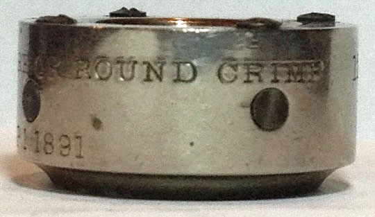 BGI, must have considered it important enough to allow
shotgunners the opportunity to have the choice.
Knowing that the four pins, the bases of which look
like dark 'spots' around the perimeter of the head in the pictures, could be
reversed, I was determined to figure out how that was accomplished. I fooled
with it for a bit and decided that the head had to be removable to be able
to get at the pins, but figuring out how to remove it without breaking the
tool eluded me.
BGI, must have considered it important enough to allow
shotgunners the opportunity to have the choice.
Knowing that the four pins, the bases of which look
like dark 'spots' around the perimeter of the head in the pictures, could be
reversed, I was determined to figure out how that was accomplished. I fooled
with it for a bit and decided that the head had to be removable to be able
to get at the pins, but figuring out how to remove it without breaking the
tool eluded me.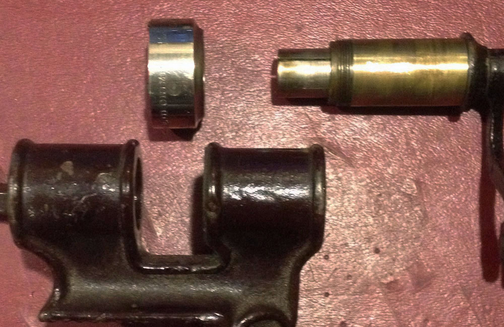
 the patent specifications as difficult to understand as possible, they tend
to be nearly impossible for those among us with less obtuse thinking to
interpret. It's the patent drawings that we generally have too depend upon
if we are going to get anything at all out of the
patent. Once I had convinced myself that the crimping head was screwed to
the shaft of the handle (note the threads on figures 8
and 15 at the top of the first page of the patent drawings) and that I
wouldn't break anything by holding the head securely and turning
the handle counter-clockwise, removing it and figuring
how to make the changes necessary to produce both
crimps was pretty easy.
the patent specifications as difficult to understand as possible, they tend
to be nearly impossible for those among us with less obtuse thinking to
interpret. It's the patent drawings that we generally have too depend upon
if we are going to get anything at all out of the
patent. Once I had convinced myself that the crimping head was screwed to
the shaft of the handle (note the threads on figures 8
and 15 at the top of the first page of the patent drawings) and that I
wouldn't break anything by holding the head securely and turning
the handle counter-clockwise, removing it and figuring
how to make the changes necessary to produce both
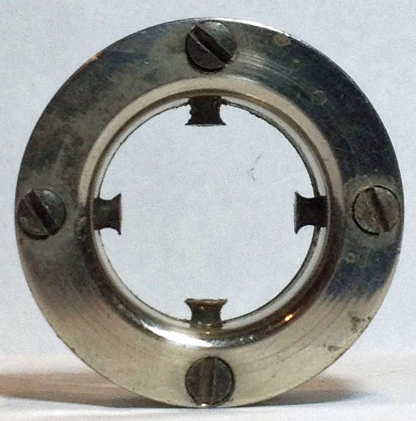
crimps was pretty easy.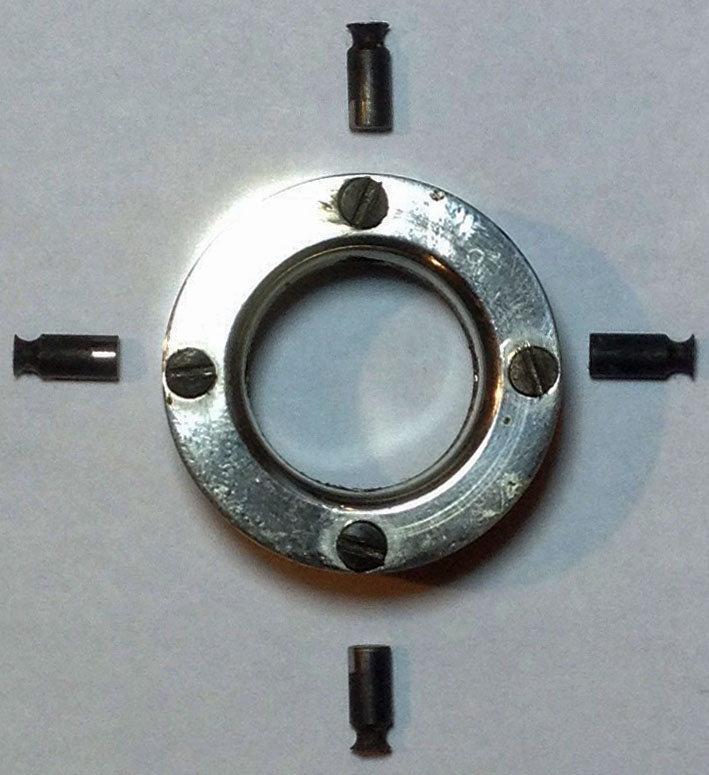 photo),
it becomes readily apparent that the key to the different crimps would be
the four pins that can be seen extending into the center opening of the
crimping head (upper right photo); as positioned in the head, the pins are set to produce
photo),
it becomes readily apparent that the key to the different crimps would be
the four pins that can be seen extending into the center opening of the
crimping head (upper right photo); as positioned in the head, the pins are set to produce
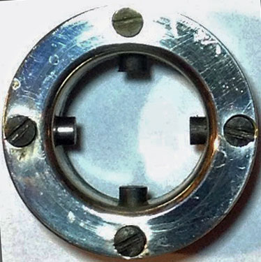 rounded
crimps. By backing out the four set screws that hold the pins securely in
the head, the pins can be removed, reversed (as shown in the photo to the
left) and slipped back in the head. Tightening the set screws completes the
process, leaving the pins in the position to make square crimps (as shown in
the picture to the right).
rounded
crimps. By backing out the four set screws that hold the pins securely in
the head, the pins can be removed, reversed (as shown in the photo to the
left) and slipped back in the head. Tightening the set screws completes the
process, leaving the pins in the position to make square crimps (as shown in
the picture to the right). 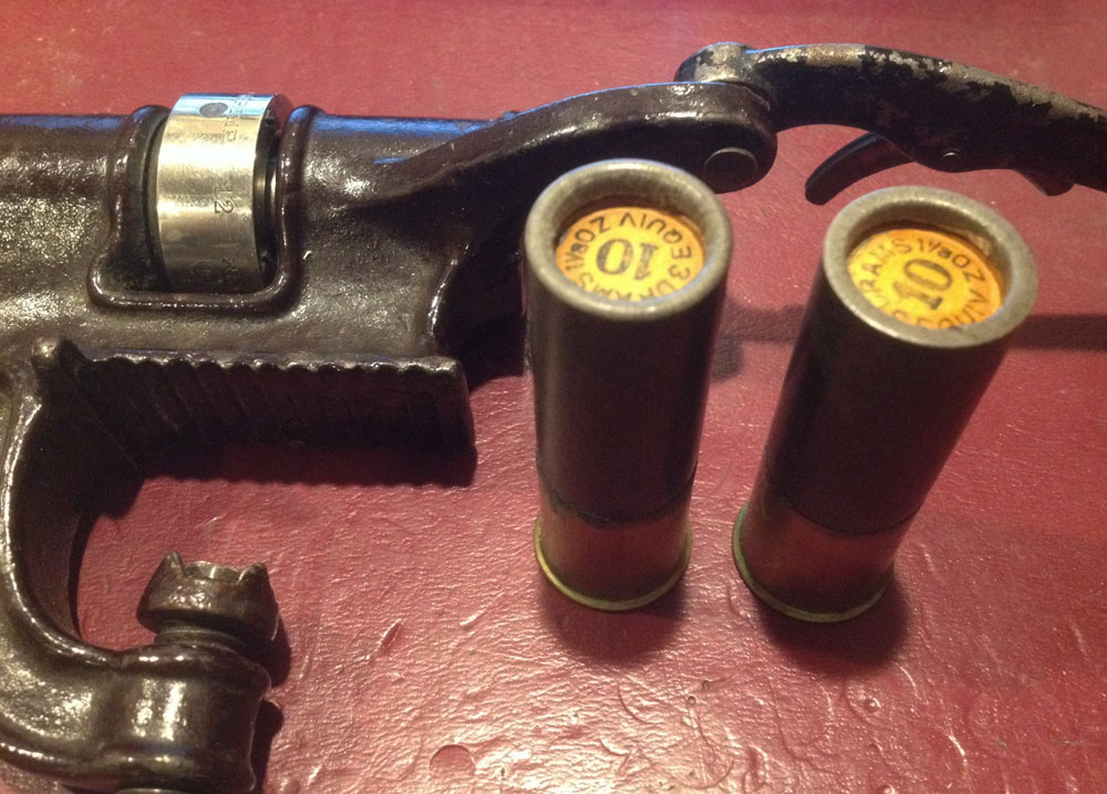
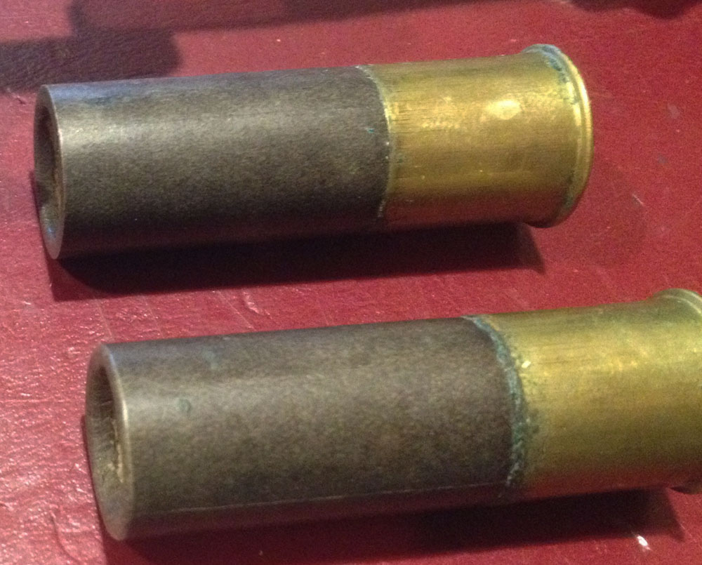 So,
now that I had the crimper all figured out, how well
did it work? Quite well, in my opinion; the shells in
these two photos show the different crimps. The square crimp is on the right
in the picture on the left, and on the top in the picture on the right.
So,
now that I had the crimper all figured out, how well
did it work? Quite well, in my opinion; the shells in
these two photos show the different crimps. The square crimp is on the right
in the picture on the left, and on the top in the picture on the right.